
GCN-1000 High Purity Nitrogen Generator Instruction Manual
2021-05-09
GCN-1000 High Purity Nitrogen Generator Instruction Manual Beijing Institute of Analytical Technology
Warning:
1. Please read this manual carefully before using the instrument!
2. The instrument should be made of pure and constant pressure air. Never operate without electrolyte! So as not to cause the consequences of the electrolyte pool can not be repaired.
3. Never operate the nitrogen generator while the air source is not connected.
4. Please clean the electrolyte before shipping and cover the inner lid of the liquid storage tank! In order to avoid corrosion of the chassis and internal components during transportation, the instrument is scrapped.
5. If the product is updated, the internal structure of the instrument is subject to change without notice!
note:
1. This manual applies to the GCN-1000 model.
2. Slowly pour the electrolyte into the reservoir when adding electrolyte. Always observe the electrolyte water level line. To the lower limit, add pure water or double distilled water immediately.
3. After replacing the filler in the filter, be sure to tighten the filter cover and tighten the filter and filter base to avoid air leaks.
The company has passed ISO9001:2000 quality management system certification products passed the national analytical instrument quality supervision and inspection center testing products passed the national standard substance testing center testing products won the ministerial level scientific and technological progress second prize product China patent number.3
The products in the World Bank International Tender "ITC-943026" project were adopted by the UNDP "ICEB-Q91211" project.
Directory I, company introduction 1
Second, product overview 1
Third, the name of each part of the instrument 2
Fourth, the installation and use of the instrument 2
Fifth, the working principle and characteristics of the instrument 5
Six, the main technical parameters 7
Seven, the complete set of instruments 7
Eight, the manufacturer's guarantee 8
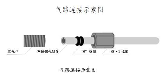
Nine, Figure 1 schematic diagram of gas path connection 8
X. Figure 2 Fault causes and troubleshooting methods of the instrument 9
I. Company Introduction Beijing Hewlett-Packard Analytical Technology Research Institute was established in 1994. It is a high-tech enterprise integrating science, industry and trade. It is the largest manufacturer of gas chromatograph generators in China. Various flow single-unit machines such as high-purity hydrogen, high-purity nitrogen, and low-noise air source, and various related combination machines. The series is full and there are many varieties. Recently, an ultra-pure hydrogen purification instrument for scientific research (hydrogen purity up to 99.99999%), a pure oxygen generator, and a thermal analyzer have been introduced. Our small-scale automatic hydrogen station, which is the first in China, solves the problem of safe centralized hydrogen supply in the central laboratory.
We adhere to the quality first, customer-oriented service standards, products throughout the country, and exported to Norway, Argentina, South Korea, Ukraine and other 18 countries and regions.
Second, the product overview
The GCN-1000 nitrogen generator adopts the latest technology of our company and can fully meet the gas chromatograph produced by any model at home and abroad.
The GCN-1000 type nitrogen generator is a nitrogen-making technology that uses pure air as a raw material gas and uses an electrocatalytic method for air separation. The catalytic layer uses a PCAN carrier and a noble metal catalyst to greatly improve the gas purity.
The GCN-1000 nitrogen generator is fully programmed to produce gas pressure and flow stability.
The GCN-1000 nitrogen generator is tested by the National Standard Gas Detection Center and the National Analytical Instrument Quality Supervision and Inspection Center.
Third, the name of each part of the instrument
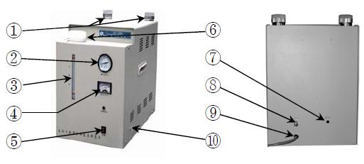
1, nitrogen purification tube
2, work pressure indicator
3, liquid level indication
4, the flow display
5, the power switch
6, electrolyte storage tank
7, air import
8, nitrogen outlet
9, the power cord
10, emptying valve
Fourth, the installation and use of the instrument
1. Start preparation
a. Take the instrument out of the box, check for damage caused by improper transportation, check whether the spare parts, certificate and warranty card of the instrument are complete.
b. Electrolyte:
i. Remove all the potassium hydroxide from the spare parts into a container, then add 500 ml of double distilled water or deionized water as the mother liquid, stir well until the electrolyte is completely cooled and set aside.
Ii. Open the reservoir lid of the instrument and remove the inner lid. The inner cover is used to prevent leakage during transportation. Please keep the inner cover for use when transporting again.
The front of the instrument
Iii. Pour the cooled electrolyte (mother liquor) into the liquid storage tank, and then continue to add secondary distilled water or deionized water. Do not exceed the upper limit water level line and do not lower than the lower limit water level line. Screw on the cover and use it after 10 minutes.
2. Self-test of the instrument: (Do not connect with the chromatogram.) When using the generator for the first time, please perform self-test on the instrument itself. The steps are as follows:
a. Remove the air source air outlet and the sealing nut of the nitrogen generator air inlet (save it for future self-test instrument), connect them with a Φ3 air pipe, and do not leak air. .
b. Start the air source first, when the pressure indication of the air source rises, and the pressure of the nitrogen generator rises slowly with the pressure of the air. When the air pressure reaches 0.4 MPa and the nitrogen pressure is close to 4 Kg/cm2 (about 0.4 MPa), the nitrogen generator power switch is turned on again. Open the venting valve for a period of time. When the nitrogen flow indication (pointer table) reaches about 1000, close the venting valve. The pressure indication (pressure gauge) should be 4Kg/cm2 (about 0.4MPa) within 5 minutes, and the digital flow rate gradually shows. Decrease to "0", indicating that the instrument system is working properly and the self-test is qualified.
c. If you suspect that the generator is faulty during use, you can use this method for self-test.
If you have any questions, please contact the technical department of our institute. Contact number to 30
3. Use of the instrument:
a. Remove the sealing nut from the air outlet on the back of the nitrogen generator. (Please save it for future self-test instruments.)
b. Connect the gas outlet of the self-tested nitrogen generator to the nitrogen inlet of the chromatograph with an outer diameter Φ3 gas pipe, tighten the nut, and the sealing performance must be good.
c. Turn on the air source switch first, then turn on the nitrogen generator switch, open the venting valve at the same time, drain the operation for 20-30 minutes (to ensure the purity of nitrogen), and then tighten the venting valve to work normally. After each boot, you should first run empty for 20-30 minutes.
d. When using the instrument, please pay attention to whether the flow display is consistent with the gas consumption of the chromatograph. If the flow display exceeds the actual amount of the instrument, stop the leak detection. For the method, please refer to the cause of the fault and the troubleshooting method of the instrument, and then use the self-test method to pass the test.
e. After the power is turned off after each work, open the venting valve and do not turn it off. Wait for the next time you turn it on, then run it for 20-30 minutes before turning it off. Special reminder here.
f. The instrument is equipped with two filters, the first stage filter is equipped with color changing silica gel, and the second stage filter is equipped with molecular sieve. During use, check whether the silica gel in the filter is discolored through the observation window. If it is discolored, please replace or regenerate it immediately. The method is as follows: unscrew the filter, unscrew the top cover of the filter, replace the silica gel, tighten the top cover of the filter, and screw the filter onto the base. Also check for leaks.
Recommendation: Replace the color changing silica gel three times and replace the molecular sieve once.
g. After using the instrument for a period of time, the electrolyte will gradually decrease. When the electrolyte level is close to the lower limit, it should be replenished in time. Only double distilled water or deionized water should be added at this time. Do not exceed the upper limit water line when adding liquid. (The concentration of potassium hydroxide used in the nitrogen generator is about 10%.)
h. Do not operate the nitrogen generator when it is not connected to an air source.
i. It is forbidden to dismantle the electrolytic cell by yourself to avoid the consequences of irreparable repair.
j. If the instrument needs to be transported, please wash the electrolyte in the liquid storage tank with ear-washing balls.
Note: There is still a residual amount of electrolyte inside the electrolytic cell, and the instrument is tilted forward by 90°. At this time, the remaining amount of electrolyte flowing into the barrel is sucked by the ear wash ball, and then the inner cover is closed, and the outer cover is tightened. It can be sealed and transported.
Fifth, the working principle and characteristics of the instrument:
working principle:
a. The instrument is made according to the principle of air separation by electrocatalysis. The electrolytic cell is designed by using the reverse process of the fuel cell.
b. As the pressure-stable and pure raw material air enters the electrolytic cell, the oxygen in the air is adsorbed at the cathode to obtain electrons, react with water to form hydroxide ions and migrate to the anode, and finally lose electrons to precipitate oxygen at the anode. Therefore, the oxygen in the air is continuously separated, leaving only nitrogen gas to be output with the gas path.
Instrument features:
a. Program control: The instrument's control system uses a dedicated chip. All work processes are controlled by the program. Automatic constant pressure, constant current, nitrogen flow can be fully adjusted according to the dosage of 0-1000ml/min.
b. Advanced technology: The electrolytic cell adopts vertical single-surface double cathode, HP's latest membrane separation technology, and the catalytic layer uses PCAN carrier and precious metal catalyst to make the electrolytic cell have high catalytic efficiency, large gas production and high nitrogen purity. The electrolysis cell has been subjected to high-pressure and high-current aging experiments for more than 100 hours before leaving the factory, which makes the performance and working state of the electrolytic cell extremely stable.
c. Three-stage catalysis: In addition to the second-stage catalysis in the two-stage catalysis in the electrolytic cell, the catalyst is selected from a new noble metal, so that the oxygen content of the output nitrogen is less than 3 PPM.
d. Low nitrogen production humidity: Ultra-high molecular weight permeable membrane separation technology and effective dehumidification device are adopted, thus reducing the original humidity and automatically discharging water after shutdown. The metal polymer dehumidification and two-stage adsorption are used to greatly improve the purity of nitrogen.
e. Convenient operation: no need to transport cylinders, save the burden of handling cylinders, just turn on the power switch to produce nitrogen. It can be used continuously or intermittently, and the nitrogen production is stable without attenuation.
f. Safe and reliable: equipped with safety devices, sensitive and reliable.
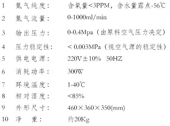
Six, the main technical parameters:
Seven, the complete set of instruments All instruments include the following:
1 nitrogen generator 1
2 Spare parts 1 Ear-washing ball (with Φ4 stainless steel tube) 1 set 2 Potassium hydroxide analytical pure (300g) 1 bottle 3 Filter seal (Φ14×2.4) 2 4 filter seals (Φ26×2.4) 2 5 Filter seal ring (Φ32×2.4) 2 6 gas path seals (Φ6×1.9 or Φ6×5) 10(5) 7 interface nuts 8 copper gas pipe (M8×1)
Φ3
2
2 meters
3 Installation instructions 1
4 product certificate 1
5 product warranty card 1
Eight, the manufacturer's guarantee:
Under the conditions of the user's compliance with the use regulations, within one year from the date of delivery to the user by the manufacturer, the product may be damaged or not used properly due to poor quality, and we will repair or replace it for free. (The electrolytic cell is guaranteed for three years)
If you have any questions, please contact our technical service center, telephone number 68033421 to 30
Nine, Figure 1
Gamma lab nitrogen generator is suitable for lab use, it makes use of pressure swing adsorption technology, separating and collecting nitrogen from air. It is easy to operate, plug and play, one simple push on starting button, nitrogen generator begin to work.

Laboratory nitrogen generator is one kind of cabinet nitrogen generator. Its size is within 850 x 920 x 1100 mm, weight within 155 kg. Its details are as below:
2 Detailed technical specification
2.1 Compressed air consumption
The generator consumes a maximum of 115 slpm of compressed air to generate the required N2 flow. Air source is not included in this product.
2.2. Air supply pressure
Minimum air supply pressure shall be externally regulated to 600 kPa.
2.3. Air quality
This Generator is provided with one full set of FESTO filters, the air supplied to the Generator still need to be dry and oil-free.
2.4. N2 output
2.4.1. Quantity of N2 generate: the generator is capable of deliver 25 slpm nitrogen.
2.4.2. Delivery pressure: the generator delivers N2 at a pressure greater than 450 kPa.
2.4.3. O2 contamination level: O2 level in the N2 stream is not exceed 0.5%, and does not vary from peak to trough by more than 5% of the absolute concentration.
2.5 Dimensions
With package, the Generator size: 850 mm (Length)x 920 mm (width)x 1100 mm(height).
2.6 Weight
With package, the Generator weight is not more than 155 kg.
2.7 Wheels
The Generator is fitted with 2 fixed wheels at the rear and 2 swivel wheels with brakes at the front
2.8 Connection to power supply
The Generator has a panel mounted connector on the rear panel
• Current capacity at maximum temperature 2.5A<Imax<3.5A ( the power supply is capable of supplying 2.5A nominal)
• Jack plug, 5.5 x 2.5 x 9.5 mm, positive on the centre pin
• Maximum operating voltage at maximum temperature 30VDC.
• Minimum number of insertions/extractions while maintaining contact resistance specification AND without mechanical failure: > 5000
• Maximum contact resistance after specified minimum insertions: 30milliohms maximum
• Insulation resistance: min 100MegaOhms after environmental and durability tests
• Dielectric withstand Voltage : Min 500V for 60s
• Operating temperature range: -20 deg C to +70 deg C
2.9 Indicator
The Generator has a pushbutton illuminated switch on the front panel
• Button to be flush mounting or recessed into a bezel to avoid damage
• High corrosion resistance, either plastic or stainless steel body
• No symbol on button
• Size of button and bezel to be ~ 22mm to 30mm
• Mechanical Endurance : > 1000000 activations without mechanical failure
• Electrical Endurance : > 100000 cycles at maximum current and maintaining maximum specified contact resistance• Action mechanism : push on – push off
• Current handling capability : 4A DC min break, 4A DC min Make, inductive load (double the maximum expected current demand to give good lifetime)
• Maximum DC Working voltage : at least 40V DC
• Illumination type and color : LED, green
• Illumination Operating voltage: 24VDC
• Operating Temperature Range: -20deg C to +70 degC
• Terminal type : either screw terminal or 6.5mm spade type terminals
2.10. Solenoids
The solenoids on the gas control valves is 24 VDC.
2.11. Operation
2.11.1. Operating cycle
A typical operating cycle for the Generator is 1 start per day and then run for 8 hours per day, which is equivalent to 2000 hours of operation per year. Depending upon the particular site, operating time could be anywhere between 0 and 24 hours per day.
2.11.2. Operation at shutdown
When the power is turned off, the pressure vessels is maintained in the pressurized state by closing the two exhaust valves.
2.12. Start up
2.12.1. Start up time
Start up times means the time from start up to producing qualified nitrogen.
The time to complete start up is less than 15 minutes.
2.13. Gas connections
The two external gas connections on the Generator, Air In and N2 Out, are constructed from brass and are to suit ¼" (6.35 mm) OD tubing. There are labeling in English next to these connections, [Air In" and [N2 Out", as part of the rating label.
2.14. Environmental requirements
2.14.1. Operating temperatures
The Generator is normally operated within performance specification over the temperature range:
10ºC - 35ºC from 0 – 3000 m, and 10ºC - 25ºC from 3000 – 4500 m
The Generator can operate safely over the temperature range:
5ºC - 35ºC from 0 – 3000 m, and 5ºC - 25ºC from 3000 – 4500 m
2.14.2. Noise level requirements
Noise level from the Generator is less than 72dBa at 1m distance. This is achieved by fitting silencers on the exhaust vents.
2.15. Life Requirements
The Generator can operate with a mean time between failure of 5 years minimum.
Lab Use Nitrogen Generator, Laboratory Nitrogen Generator, Laboratory Nitrogen Gas Generator, Laboratory Use High Purity Nitrogen Generator
Sports Floor,Plastic Floor Co., Ltd. http://www.gammagases.com